Descripción
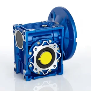
EP-NRV-E110 Aluminium Coaxial Worm Gearbox — Solid Shaft Input, Inline Output
The EP-NRV-E110 is a large-frame inline shaft-coupled aluminium worm gearbox and a large-frame inline shaft-coupled unit in the NRV-E series, built around a 110 mm worm gear centre distance. It represents the most specialised configuration in the four-variant series: combining the solid 38 mm solid input shaft of the NRV series with the coaxial inline output of the NMRV-E series. The result is a worm gearbox that operates as a pure inline shaft-coupled reduction stage — accepting a shaft coupling, chain sprocket, or belt pulley on the input and delivering reduced speed on the same axis at the output, with no motor flange projection at either end and no 90-degree shaft offset. This configuration is engineered for steel mill coaxial shaft trains, heavy mixer inline shaft drives, winch coaxial systems, and port inline shaft machinery where the complete drive train must maintain a single shaft axis from source to load. With output torques up to 8000 Nm, ratios from 7.5–100:1, die-cast aluminium A360 housing, and IP65 shaft sealing, the EP-NRV-E110 serves steel processing and heavy industrial inline shaft-coupled drive trains across Australia and international markets. All six mounting positions are supported for maximum installation flexibility.
Technical Specifications — EP-NRV-E110
General Specifications
| Parameter | Specification |
|---|---|
| Model Number | EP-NRV-E110 |
| Series | NRV-E — Solid input shaft, coaxial inline output |
| Centre Distance | 110 mm |
| Output Configuration | Coaxial / Inline — same axis as input shaft |
| Max Output Torque | 8000 Nm |
| Reduction Ratios | 7.5–100:1 |
| Input Shaft Diameter | 38 mm solid |
| Input Shaft Keyway | 10×5.0 mm |
| Input Shaft Tolerance | h6 (precision ground) |
| Max Input Shaft Radial Load (Fri max) | 1700 N |
| Output Shaft Diameter | 50 mm (coaxial) |
| Max Recommended Input Power | 1.1 kW |
| Housing Material | Die-cast aluminium alloy A360 |
| Worm Wheel Material | Phosphor bronze |
| Worm Shaft Material | 20CrMnTi case-hardened steel, ground |
| Surface Treatment | Baked enamel paint (RAL 5010 blue) |
| Lubricant | ISO VG 220 worm gear oil, ~2.5 L |
| IP Rating | IP65 (shaft seals standard) |
| Ambient Temperature | -10°C to +40°C standard; up to +60°C with synthetic oil |
| Max Input Speed | 1,400 rpm (recommended); 1,800 rpm (max) |
| Approx. Weight | ~28 kg |
| Mounting Positions | B3, B6, B7, B8, V5, V6 |
| Output Configurations | Coaxial solid shaft (standard) / Coaxial output flange (FL) |
| Note | Double output shaft (DZ) not available — coaxial geometry |
| Standards | ISO 9001, CE marking |
Performance Selection Data (1,400 rpm Input)
| Ratio (i) | Output Speed (r/min) | Output Torque (Nm) | Input Power (kW) |
|---|---|---|---|
| 10:1 | 140 | 4285 | 1.1 |
| 15:1 | 93 | 4905 | 1.1 |
| 20:1 | 70 | 5399 | 1.1 |
| 25:1 | 56 | 5816 | 1.1 |
| 30:1 | 47 | 6181 | 1.1 |
| 40:1 | 35 | 6803 | 1.1 |
| 50:1 | 28 | 7607 | 1.1 |
Core Features & Benefits
◯Solid Shaft Input + Coaxial Output — The Ultimate Inline Shaft Drive
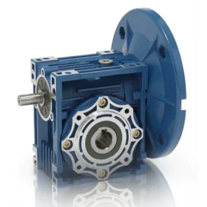
The EP-NRV-E110 combines both specialised features: a solid 38 mm solid input shaft (no motor flange) and a coaxial inline output shaft. This dual configuration produces the most compact possible inline shaft-coupled worm gearbox — ideal for multi-stage gear trains and inline shaft drives where both ends must be on the same axis with no flange projection.
△Shaft-to-Shaft Inline Reduction — No Axis Deviation
Unlike right-angle units, the NRV-E110 receives and delivers power along a single axis. Solid input shaft accepts couplings, sprockets, and pulleys; coaxial output connects to the driven load shaft. The result is a reduction stage that slots into any inline shaft train without introducing a 90-degree offset or motor flange bracket at either end.
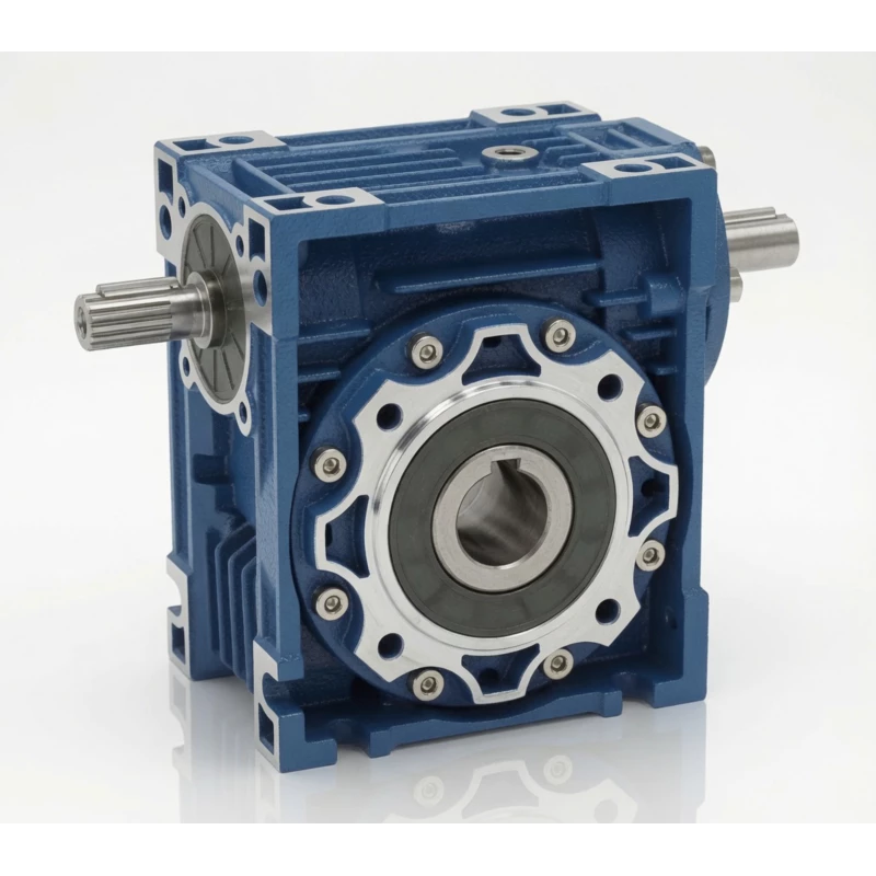
◆Corrosion-Resistant Die-Cast Aluminium Housing
A360 die-cast aluminium provides inherent corrosion resistance for food processing, coastal, chemical, and humid environments. Baked enamel surface finish adds UV protection. 30–40% lighter than cast iron equivalents — critical for weight-sensitive elevated or moving structures.
■Identical Torque to All NRV{size} Variants
The NRV-E110 delivers the same 8000 Nm maximum output torque as the standard NRV110, NMRV110, and NMRV-E110 — all four variants share the same precision-ground worm set and phosphor bronze wheel. Only input/output configuration differs.
▶Static Self-Locking at Ratios ≥ 40:1
At 40:1 and above, worm geometry prevents back-drive under static load — useful in positioning, conveyor braking, and crane holding applications within inline shaft drive trains. Identical self-locking behaviour to all other NRV/NMRV variants using the same worm set.
●Full Mounting Position Flexibility — Six Orientations
B3, B6, B7, B8, V5, V6 mounting positions available. For V5/V6 vertical orientations, use the NRV-E lubrication guide (not standard NRV) to set the correct fill level for the coaxial internal geometry. Coaxial layout is particularly effective in vertical inline drive train columns.
All Four 110-Frame Variants — Which One Is Right for You?
All four variants in the 110-frame series share the same worm set, output torque ratings, and housing. Select based solely on input type (solid shaft vs IEC flange) and output direction (coaxial vs right-angle).
| Feature | EP-NRV-E110 ▶ | EP-NMRV-E110 | EP-NRV110 | EP-NMRV110 |
|---|---|---|---|---|
| Input Type | Solid shaft (no flange) | Hollow bore IEC flange | Solid shaft (no flange) | Hollow bore IEC flange |
| Output Direction | Coaxial / Inline | Coaxial / Inline | 90° Right-angle | 90° Right-angle |
| Max Output Torque | 8000 Nm | 8000 Nm | 8000 Nm | 8000 Nm |
| Best Use Case | Inline shaft-coupled gear trains | Inline motor-driven drives | Shaft-coupled right-angle drives | Direct motor right-angle drives |
| Motor Flange | No | Yes (IEC) | No | Yes (IEC) |
| Lateral Width | Narrowest inline | Narrow inline | Wider (90° shaft offset) | Wider (90° shaft offset) |
| Double Shaft DZ | Not available | Not available | Available | Available |
| Housing | Aluminium A360 (same) | Aluminium A360 (same) | Aluminium A360 (same) | Aluminium A360 (same) |
Application Sectors — EP-NRV-E110
The EP-NRV-E110 is the preferred choice for the following inline shaft-coupled drive system types where the solid input shaft and coaxial output together eliminate both motor flange projection and 90-degree shaft offset.
⚘ Steel Mill Coaxial Shaft Trains
Suitable NRV-E large frame solid shaft worm gearbox steel mill.
⚙ Heavy Mixer Inline Shafts
Suitable coaxial shaft worm reducer heavy mixer inline.
⚚ Winch Coaxial Systems
Suitable inline shaft worm gearbox winch coaxial drive.
⚒ Port Inline Shaft Machinery
Suitable NRV-E worm reducer port machinery inline shaft.
⚛ Large Fan Inline Shaft Drives
Suitable large solid shaft coaxial worm gearbox fan drive.
Selection Guide, Mounting Positions & Shaft Details
How to Select the Correct Ratio
- Calculate required output torque: M₂ = 9,550 × P (kW) / n₂ (rpm), multiplied by service factor (fs = 1.0–2.5 per duty class).
- Determine actual input shaft speed: For belt/chain-driven inputs, n_input = n_primary × (D_primary / D_NRV-E). Use the actual input speed — not the primary motor rated speed.
- Find your ratio: i = n_input / n_output. Select the closest from 7.5–100:1.
- Confirm torque capacity and input radial load: Rated torque must exceed M₂ × fs. Calculate input shaft radial load from belt/chain tension and verify against Fri max = 1700 N. Step up to EP-NRV-E130 if either limit is exceeded.
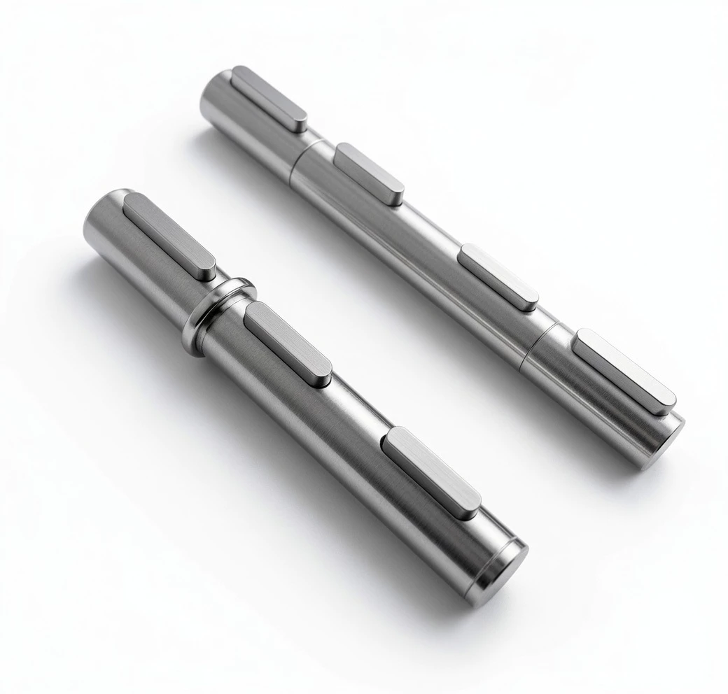
Input & Output Shaft Details
Input shaft: 38 mm solid solid | Keyway: 10×5.0 mm | Tolerance: h6 | Max radial load: 1700 N
Output shaft: 50 mm solid, coaxial (same axis as input) | With keyway | Standard solid shaft or FL flange option
50 mm with keyway on same axis as input. Default supply.
Direct bolt-on flanged connection coaxial with input axis. Suffix: FL.
Double output shaft (DZ) is NOT available in the NRV-E coaxial series.
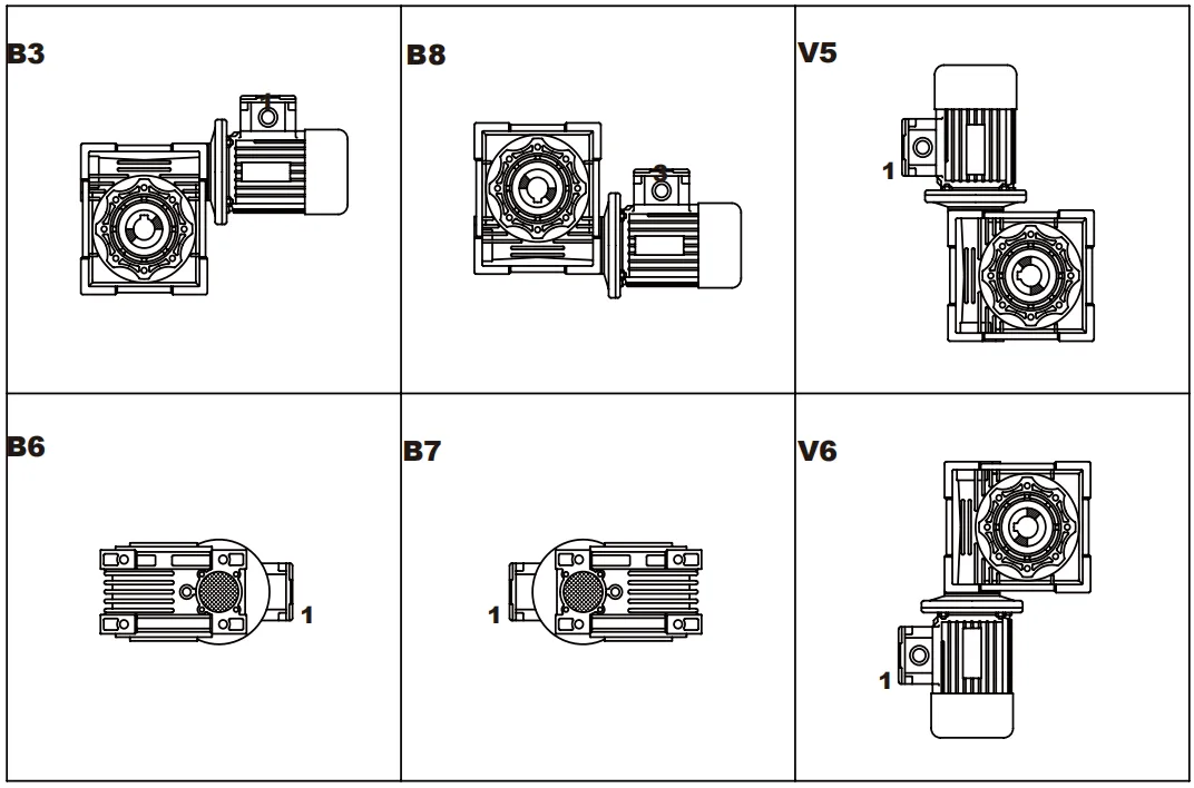
Mounting Positions
| Position | Description | Shaft Orientation | Oil Level Note |
|---|---|---|---|
| B3 | Horizontal foot mount | Inline horizontal shaft — input and output facing opposite ends | Standard fill level — default |
| B6 | Foot mount, output shaft down | Inline vertical shaft downward | Reduce oil by ~15% |
| B7 | Foot mount, output shaft up | Inline vertical shaft upward | Increase oil by ~15% |
| B8 | Foot mount, 180° rotated | Inline horizontal reversed | Standard fill level |
| V5 | Flange mount, shaft down | Inline vertical downward | Reduce oil — use NRV-E lube guide |
| V6 | Flange mount, shaft up | Inline vertical upward | Increase oil — use NRV-E lube guide |
Important: For NRV-E V5/V6 vertical orientations, use the NRV-E lubrication diagram to set the correct oil fill level. The coaxial internal geometry requires a different fill level from both the standard NRV and NMRV-E guides.
Frequently Asked Questions — EP-NRV-E110
▶ What distinguishes the EP-NRV-E110 for steel mill coaxial shaft trains?
Steel rolling mills require each drive stage in the roll train to maintain a common shaft axis through the rolling stand. The NRV-E110’s solid 38 mm input shaft accepts the upstream coupling, and the coaxial 50 mm output shaft continues to the downstream roll — delivering up to 8,000 Nm while maintaining the inline shaft axis throughout the entire mill drive train.
▶ What is the input shaft specification of the EP-NRV-E110?
Solid 38 mm input shaft with 10×5.0 mm keyway, h6 tolerance. Maximum input shaft radial load (Fri max) is 1,700 N. For heavy chain-driven inputs, provide a bearing support bracket near the sprocket. Use a flexible disc or gear coupling for motor-to-shaft connections to accommodate thermal expansion and minor misalignment.
▶ How does the aluminium housing of the EP-NRV-E110 perform in hot steel mill environments?
The A360 die-cast aluminium housing dissipates heat approximately 3× faster than cast iron (~160 W/m·K vs ~50 W/m·K), keeping inline shaft train operating temperatures 10–15°C lower under equivalent load. Use synthetic ISO VG 220 oil for ambient temperatures up to 60°C.
▶ What is the maximum input speed for the EP-NRV-E110?
1,400 rpm recommended; 1,800 rpm absolute maximum. For inline shaft trains driven by VFD-controlled motors via flexible couplings, operate between 700–1,400 rpm to maintain adequate lubrication circulation within the coaxial housing.
▶ Are there any restrictions on output shaft loading for the EP-NRV-E110?
The 50 mm coaxial output shaft is rated for the same radial and axial loads as the standard NRV110. For heavy radial loads from large sprockets or gears mounted directly on the output shaft, calculate the resultant force and verify against the rated output shaft radial load capacity. For combined heavy radial and axial loads, contact our engineers for bearing life verification.
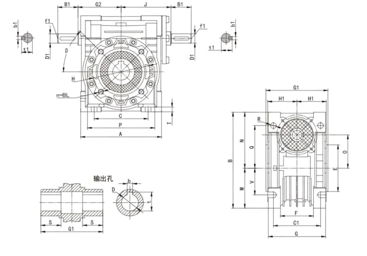
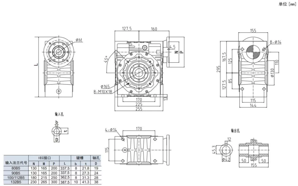
▶ What are the overall assembly dimensions of the EP-NRV-E110 inline drive?
Housing body: 255 mm (L) × 295 mm (W) × 170 mm (H). The coaxial output extends the total axial length by approximately 60–70 mm compared to the right-angle NRV110. Plan the full inline assembly length (input coupling + gearbox + output coupling) when laying out the drive train within the machine frame.
Customer Reviews
★★★★★
“The EP-NRV-E110 is installed as a reduction stage in the inline drive train of our cold-rolled coil slitting line. Solid 38 mm input shaft connects via disc coupling to the primary gearbox output, coaxial 50 mm output continues to the slitter mandrel shaft. The entire drive train runs on one axis within our compact rolling stand — 8,000 Nm delivered reliably on the heaviest stainless grades.”
Aaron Stevenson — Steel Rolling Mill Services
Australia
★★★★★
“Integrated into the inline reduction drive train of our large industrial kneader shaft systems. The NRV-E110 maintains the coaxial shaft axis from the primary motor coupling through to the kneader shaft. Aluminium thermal performance keeps the housing cool at sustained heavy loads without supplementary cooling.”
Jean-Paul Lemaire — Heavy Industrial Drives
France
★★★★☆
“Used in the inline shaft drive trains of our bulk material scraper conveyor systems at a South Island port. The NRV-E110 connects between the primary reducer and conveyor drum shaft — maintaining the compact inline drive axis. Salt-air environment has had no visible impact on the aluminium housing after two years.”
Liam Fitzgerald — Port Infrastructure NZ
New Zealand
Related Products & Accessories
⚙ Input Connection Options
Flexible jaw / disc / gear couplings for 38 mm solid shaft.
Chain sprockets (verify tension against Fri max 1700 N).
V-belt and toothed belt pulleys.
Bearing support bracket for high-tension chain/belt inputs.
⚒ Output Options
■ Coaxial solid shaft (standard, 50 mm)
■ Coaxial output flange (FL suffix)
◆ DZ double shaft not available in NRV-E series
■ Torque arm for torque reaction mounting
◆ All Four 110-Frame Variants
■ EP-NRV-E110 — this unit (shaft in, coaxial out)
■ EP-NMRV-E110 — flange in, coaxial out
■ EP-NRV110 — shaft in, 90° right-angle out
■ EP-NMRV110 — flange in, 90° right-angle out
■ EP-NRV-E130 — next frame size up
Ready to Order the EP-NRV-E110?
Request a quote, technical selection support, or enquire about OEM and distributor partnership opportunities for Australian and international markets.
▼ Distributor & OEM partnerships welcome — volume pricing available