Description
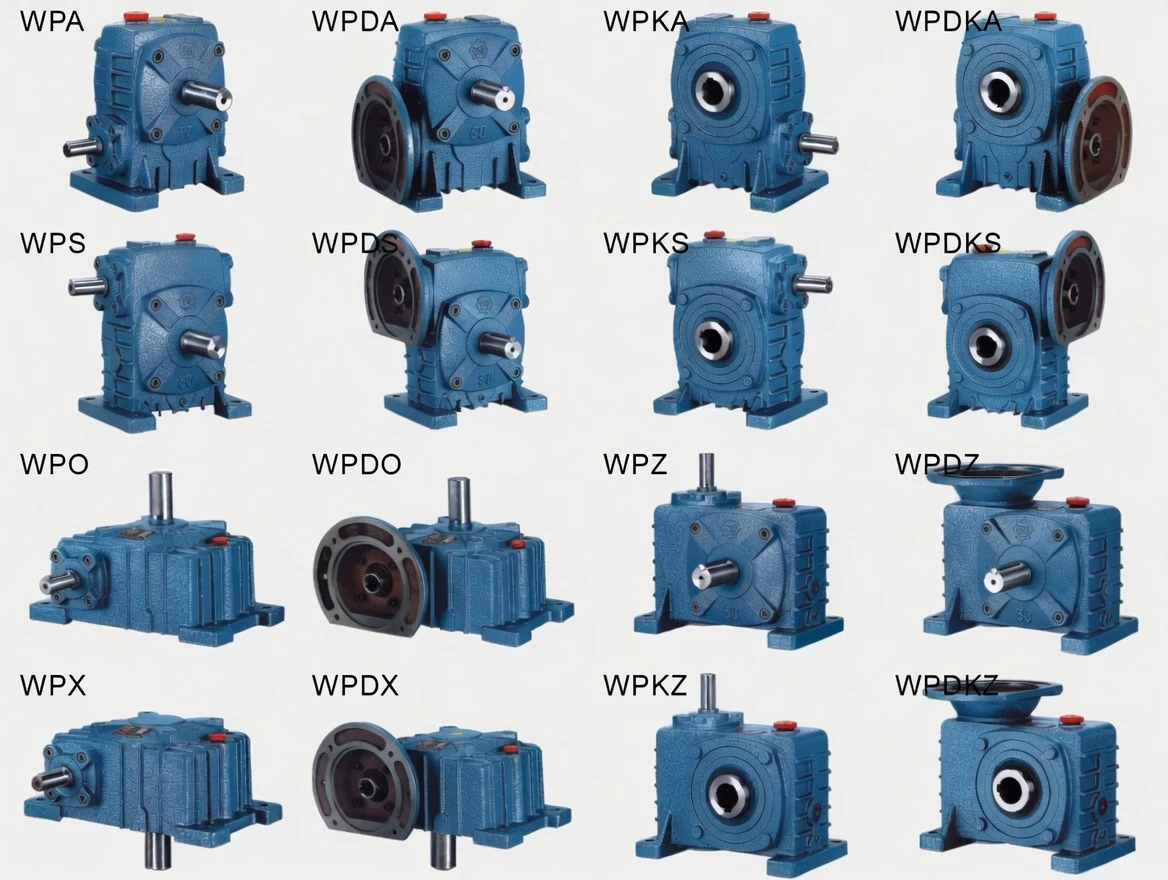
WPDKS Cast Iron Worm Gearbox — Product Overview
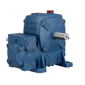
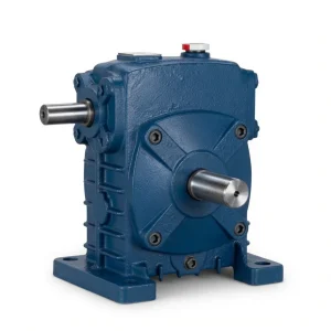
Some industrial drives push the boundaries of what standard catalogue products can provide — they need a motor to mount directly via IEC flange, the motor to enter from above (overhead installation), and the output shaft to be a hollow bore for direct driven shaft connection. Until the WPDKS, achieving this required three separate components: a separate adaptor plate, a modified gearbox, and a bespoke coupling arrangement. The WPDKS Single Speed Cast Iron Worm Gearbox is the industry’s answer to this triple-requirement challenge, combining D-split housing, K-hollow output, and S-input-from-above in a single, ISO-9001-certified cast iron unit that transforms a three-part engineering problem into a one-part solution.
Technical Specifications — WPDKS
Key Parameters
| Parameter | Specification |
|---|---|
| Series | Single Speed |
| Housing Structure | Separate split cast iron (D-type) |
| Input Configuration | Motor flange hollow bore (IEC), input from above (S-type) |
| Output Configuration | Hollow bore output (K-type) |
| Reduction Ratio | 1/5–1/60 |
| Centre Distance Size | 40–250 mm |
| Mounting | D-type split housing, IEC flange, S-input, K hollow output |
| Housing Material | FC20+ grey cast iron (GG20) |
| Worm Wheel Material | Tin-bronze alloy (ZCuSn10Pb1) |
| Worm Shaft Material | 20CrMnTi case-hardened steel, 55–60 HRC surface |
| Lubrication | N220–N320 mineral oil (−30°C to 40°C); N320–N460 (40°C to 65°C) |
| Max Oil Temperature | 95°C continuous |
| Weight Range | 5–350 kg |
| Special Feature | Triple-feature: D-split housing + K-hollow output + S-top-entry IEC flange |
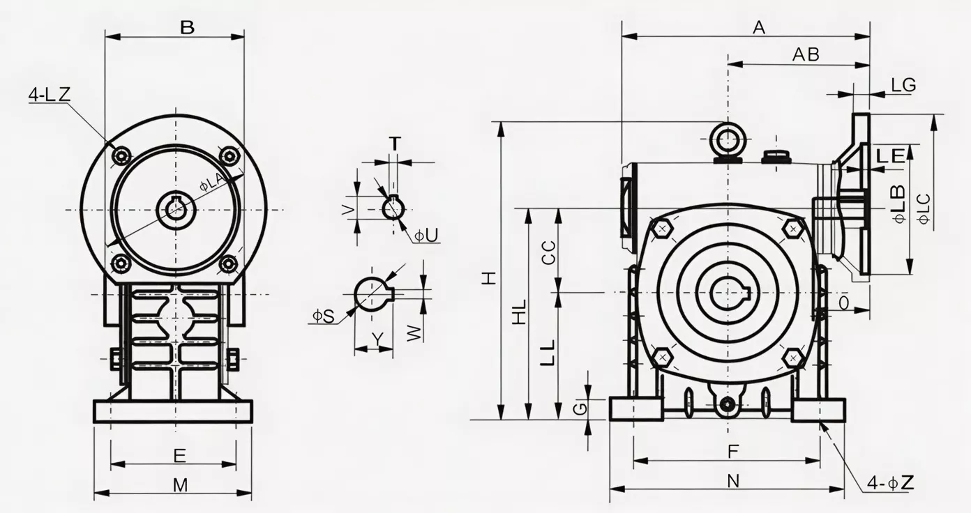
Size & Performance Data
| Size | Ratio | Input Power (kW) | Output Torque | A (mm) | AB (mm) | B (mm) | BB (mm) | Weight (kg) |
|---|---|---|---|---|---|---|---|---|
| 40 | 1/5 | 0.12 | — | 135 | 75 | 85 | 40 | 5 |
| 50 | 1/5 | 0.18 | — | 151 | 83 | 105 | 50 | 8 |
| 60 | 1/5 | 0.37 | — | 167 | 91 | 110 | 60 | 10.5 |
| 70 | 1/5–1/10 | 0.37–0.75 | — | 200/202 | 109/111 | 130 | 70 | 17 |
| 80 | 1/5–1/10 | 0.75–1.5 | — | 225 | 125 | 150 | 80 | 25 |
| 100 | 1/5–1/15 | 1.5 | — | 280 | 148 | 160 | 100 | 38 |
| 120 | 1/5–1/25 | 2.2–3.0 | — | 333 | 181 | 175 | 120 | 60 |
| 135 | 1/5–1/30 | 3.0–4.0 | — | 375 | 202 | 210 | 135 | 85 |
| 155 | 1/5–1/60 | 4.0–5.5 | — | 425/448 | 224/247 | 256 | 155 | 120 |
| 175 | 1/5–1/60 | 5.5–7.5 | — | 481 | 262 | 282 | 175 | 150 |
| 200 | 1/5–1/60 | 7.5–11.0 | — | 516/543 | 258/285 | 320 | 200 | 218 |
| 250 | 1/5–1/60 | 11.0–15.0 | — | 615 | 330 | 400 | 250 | 350 |
Product Structure
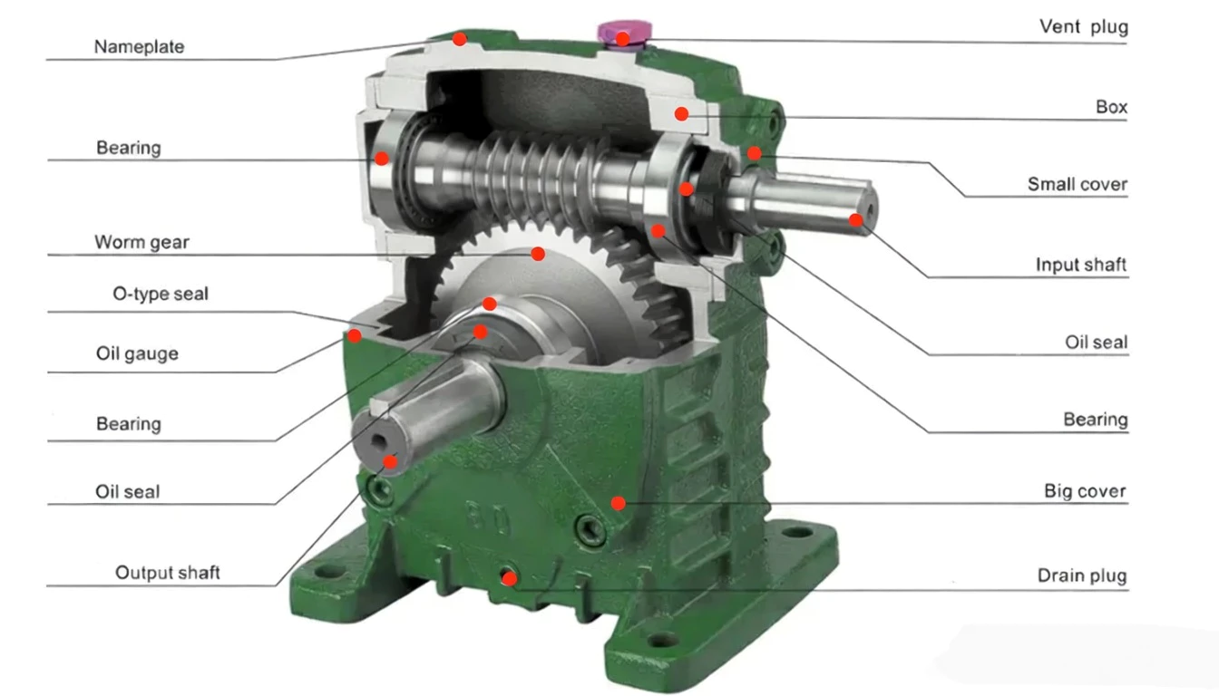
The WP series cast iron worm gearbox is built from precision-manufactured components, each selected for maximum performance and longevity:
FC20+ grey cast iron, precision-machined mounting faces, integrated air vent, oil gauge boss, and drain plug.
20CrMnTi case-hardened steel, precision-ground thread profile, 55–60 HRC surface hardness. Supported by twin tapered roller bearings.
Tin-bronze alloy ZCuSn10Pb1, precision hobbed tooth profile, press-fitted to cast iron hub. Provides superior anti-galling properties in the worm mesh.
45# alloy steel, heat treated to 250–280 HB, precision-machined keyway, supported by deep groove ball bearings or tapered rollers (size-dependent).
National oil seal lips on all shaft exits. O-ring seal on housing joints. Eliminates contamination ingress and prevents lubricant loss.
All bearings are premium-grade (C3 clearance class), selected for the specific radial and axial load profile of each shaft position and operating configuration.
Core Features & Benefits
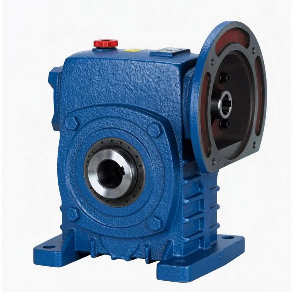
■ Triple Combination: D-Split Housing + K-Hollow Bore + S-IEC Flange from Above
The WPDKS is the most specification-rich unit in the WP single-speed range. Three distinct engineering features are combined in one housing: the maintainability of D-split, the connection simplicity of K-hollow bore, and the installation efficiency of S-IEC flange.
■ Field-Maintainable Without System Shutdown
D-split housing: remove the top cover without dismounting the motor (IEC flange remains) and without removing the driven shaft from the K-bore. All wearing parts accessible in position — the ultimate field-service configuration for overhead installations.
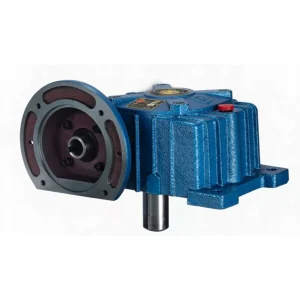
■ IEC Flange + S-Input: Motor Mounts Overhead, Bolts Direct, No Coupling
The S-type IEC flange faces upward. The motor mounts overhead, bolts directly to the flange — four bolts, no coupling, no shaft alignment. For overhead drive installations, this is the fastest and most reliable connection method available.
■ Hollow Bore Output: Zero Coupling Hardware on Output Side
The K-type hollow output bore eliminates the coupling, coupling hub, and shaft extension on the output side. Combine with the IEC flange input and the WPDKS operates with zero external coupling components on either side.
■ Oil System Optimised for Combined D+K+S Geometry
The oil fill level, air vent position, and drain plug location are all tuned for the unique internal geometry created by the D+K+S feature combination, ensuring proper lubrication in all approved mounting orientations.
■ Sizes 40–250: From 0.12 kW to 15 kW Rated Input
The full WPDKS size range covers the complete industrial drive range from fractional-horsepower laboratory drives to 15 kW heavy industrial overhead drives, all in the same triple-feature cast iron housing format.
Industry Applications — WPDKS
⚙ Complex OEM Drive Engineering
When machine specifications demand all three features simultaneously — overhead IEC motor, hollow bore output, split maintenance housing — the WPDKS is the definitive single-unit solution that replaces multi-component arrangements.
⚔ Chemical & Pharmaceutical Reactor Drives
Chemical reactor drives with ceiling-mounted motors, direct motor flange connections, and hollow agitator shaft output represent the archetypal WPDKS application — where every exposed component interface is a potential contamination or corrosion point.