Описание
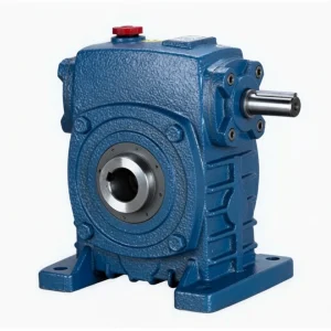
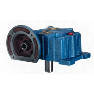
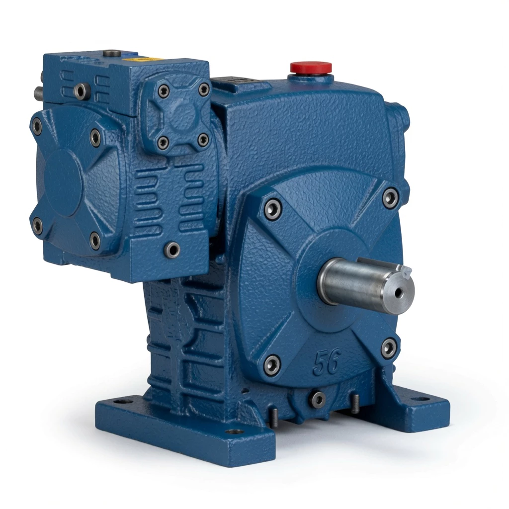
WPES Double Speed Cast Iron Worm Gearbox
Overhead motor configurations — where the motor sits above the gearbox with its shaft entering from above — combined with ultra-high reduction ratios are required by process plants with fixed overhead motor platforms, clean room equipment with ceiling-mount motors, and reactor buildings where motors must be above the drive. A single-stage WPS delivers maximum 1/60. The WPES Double Speed Cast Iron Worm Gearbox combines S-type input (motor from above) with double-stage worm reduction, delivering ratios from 1/200 to 1/900 with overhead motor geometry — eliminating a second gearbox stage from every elevated slow process drive.
Technical Specifications — WPES
Key Parameters
| Parameter | Specification |
|---|---|
| Series | Double Speed WPE+S |
| Housing | Solid integral cast iron, dual-stage |
| Input | Solid shaft (S-type, from above) |
| Output | Solid shaft (horizontal) |
| Ratio | 1/200–1/900 |
| Size Range | 40–250 combined mm |
| Mounting | Foot-mount, S-type top-entry input |
| Housing Material | FC20+ grey cast iron, dual-chamber |
| Worm Wheels | Matched pair tin-bronze ZCuSn10Pb1, both stages |
| Worm Shafts | 20CrMnTi case-hardened, 55–60 HRC, both stages |
| Lubrication | N220–N320 (–30°C–40°C); N320–N460 (40°C–65°C), both chambers |
| Max Oil Temp | 95°C continuous |
| Weight Range | 20–462 kg |
| Key Feature | Double-stage + S-type overhead input — high ratio with overhead motor geometry |
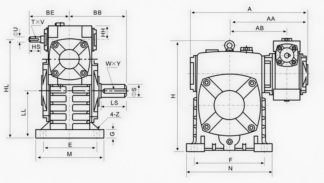
Size & Performance Data
| Size Combo | Ratio | Input (kW) | Output Torque (Nm) | A (mm) | AA (mm) | AB (mm) | BB (mm) | Weight (kg) |
|---|---|---|---|---|---|---|---|---|
| 40–70 | 1/200 | 0.48 | 250 | 286 | 195 | 153 | 131 | 20 |
| 50–80 | 1/300 | 0.65 | 350 | 297 | 197 | 144 | 142 | 27 |
| 60–100 | 1/400 | 0.95 | 500 | 363 | 231 | 175 | 169 | 44 |
| 70–120 | 1/500 | 1.64 | 840 | 408 | 256 | 193 | 190 | 73 |
| 80–135 | 1/600 | 2.5 | 1400 | 471 | 298 | 226 | 210 | 101 |
| 100–155 | 1/800 | 3.69 | 2100 | 555 | 354 | 269 | 252 | 144 |
| 120–175 | 1/900 | 5.09 | 3050 | 568 | 379 | 287 | 255 | 201 |
| 135–200 | … | 7.22 | 3950 | 662 | 425 | 318 | 319 | 293 |
| 155–250 | … | 11.71 | 6050 | 795 | 510 | 380 | 385 | 462 |
Double-Stage Product Structure
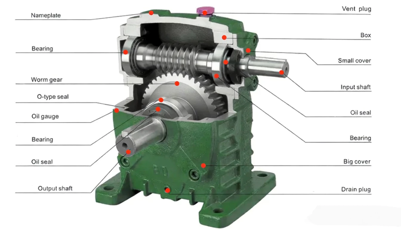
The WPE double-stage housing contains two complete worm gear stages in one precision-machined cast iron body, with two independent oil chambers:
First worm shaft and bronze wheel — receives motor power, produces first reduction. Higher-speed, lower-torque stage optimised for input speed operating conditions.
Connects primary stage output to secondary stage input. Precision-machined, supported by C3-clearance bearings, transmits intermediate torque and speed between the two stages.
Second worm shaft and bronze wheel — lower speed, higher torque. Matched-pair manufacturing with primary stage ensures consistent inter-stage noise and efficiency throughout service life.
Two oil chambers — one per stage — each filled and monitored separately. Independent optimisation of lubrication viscosity and fill level per stage is a key advantage over two-gearbox cascade arrangements.
Two air vents and two oil gauges — one per chamber — provide independent pressure management and oil level monitoring for each stage throughout operation.
Single FC20+ cast iron casting forms both chambers with no gaskets between them. Monolithic rigidity prevents inter-chamber flex that could misalign intermediate shaft bearings.
Core Features & Benefits
■ S-Input (Overhead Motor) + Double-Stage: Both Challenges in One Unit
WPES solves two challenges simultaneously: S-type upward input shaft for overhead motor configuration, and double-stage worm reduction for 1/200–1/900 ratio. Previously requiring a separate S-input adaptor plus a second gearbox stage.
■ Oil Circuit Validated for S-Input + Double-Stage Geometry
Internal oil channels, fill ports, and air vents are specifically positioned for the S-input double-stage geometry — unlike improvised solutions using standard gearboxes in non-rated orientations.
■ Same Output Torques as WPEA — No Compromise for S-Input
The S-input orientation does not reduce WPES output torque rating. Maximum torques are identical to the WPEA for the same size combination — up to 6,050 Nm at size 155–250.
■ Vertical Motor Bracket System Compatible
The WPES housing geometry accommodates standard vertical motor mounting brackets, providing complete overhead motor configuration support without custom fabrication.
■ Bilateral Input Shaft in S-Orientation
Even in the S-type overhead configuration, the input shaft accepts motor coupling from either left or right, giving installation flexibility for overhead motor positioning in confined plant spaces.
■ Primary Stage Bearings Calibrated for S-Type Input Loads
The S-type input shaft orientation places specific axial and radial loads on the primary stage input bearings. The WPES bearing selection and preload specification accounts for these S-input loads at the full double-stage torque rating.
Industry Applications — WPES
⚔ Overhead Motor Slow Process Equipment
Process plants with fixed overhead motor positions use the WPES double-stage to achieve slow output speeds without adding floor-level gearbox stages — maintaining the overhead motor layout specified by the building structure.
☵ Slow Mixing Vessels — Overhead Motor Layout
Batch vessels where overhead motor mounting is the specified design and slow agitation (1–10 RPM) is required use the WPES for a clean vertical motor stack with double-stage ratio in one housing.
⚒ Tunnel Dryer Conveyor — Overhead Motor Position
Tunnel dryer conveyor drives with overhead motor mounting and very slow belt speeds use the WPES for the S-type overhead motor geometry at extreme reduction ratios.
⚊ Elevated Platform Drive Stations
Process plant elevated motor platforms where the motor is positioned above the gearbox as a safety and maintenance requirement use the WPES double-stage for all ultra-slow drive positions.
⚛ Ceiling-Mount Slow Equipment — Restricted Floor Space
Facilities where floor space is strictly limited and motors must be ceiling-mounted above all equipment use the WPES for extreme ratio reduction with overhead motor geometry.
Why Choose WPES — Competitive Comparison
| Feature | Ever-power WPES | Alternatives |
|---|---|---|
| Input Orientation | ✓ S-type from above — overhead motor | A-type from below (WPEA) — standard |
| Overhead Motor Config | ✓ Direct — purpose-built S-input geometry | Requires adaptor bracket |
| Reduction Range | ✓ 1/200–1/900 double-stage | 1/5–1/60 single stage S-type |
| Oil Circuit | ✓ Validated for S-input + double-stage | Standard horizontal circuits only |
| Single Unit Replaces | ✓ S-adaptor + two-stage gearbox cascade | Two-stage arrangement required |
| Ceiling Space | ✓ Minimised — motor directly above gearbox | Motor alongside adds lateral width |
Quality Control & Certifications

✎ ISO 9001:2000 Certified
Every WPES is manufactured, assembled, and tested under the ISO 9001:2000 quality management framework. We were among the first in our industry category to achieve this certification.
✎ CE Marking
Full CE marking confirms compliance with EU Machinery Directive 2006/42/EC — covering safety, design standards, and manufacturing quality for mechanical power transmission equipment including double-stage worm gearboxes.
✎ Pre-Shipment Testing (Every Unit)
Noise test (below 72 dB(A) at rated load), oil leak test (30-minute pressurisation, both chambers), torque transmission test (output torque within ±5% of rated). Failed units are reworked — not shipped.
✎ Matched-Pair Manufacturing
Both worm wheel sets for each double-stage unit are manufactured in the same production batch, ensuring tooth profile consistency between primary and secondary stages. This matched-pair quality assurance is unique to our double-stage production process.
Why Choose Ever-power for WPES
We have been producing WPE series double-stage cast iron worm gearboxes for over two decades. Our matched-pair production methodology and dual-chamber quality assurance are the result of accumulated process expertise.
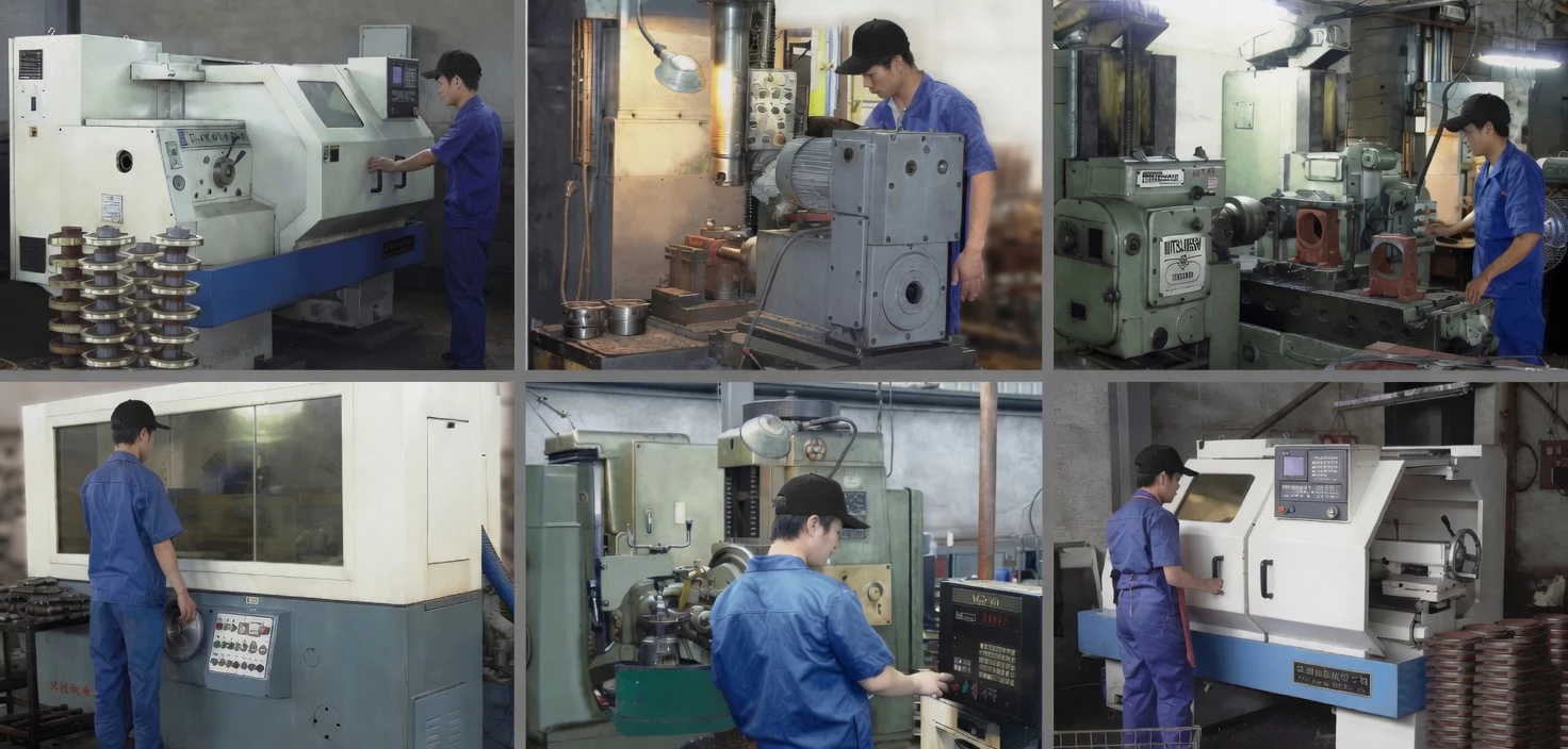
Our CNC gear grinding centres, hobbing machines, and coordinate measuring machines — sourced from the USA, Japan, Germany, and Italy — produce the precision tooth profiles required for consistent double-stage inter-stage performance.
We export to the USA, Europe, Southeast Asia, Australia, and the Middle East. Our export documentation, CE certification, and packing standards are optimised for international supply chains including pharmaceutical and food industry procurement.
Full OEM services: custom nameplating, paint colours, shaft dimensions, flange configurations, and documentation packages. We support custom double-stage specifications from concept to production release.
Our application engineers provide double-stage gearbox selection, torque calculation, oil selection guidance, and installation support. Email [email protected] with your application data for a same-day selection recommendation.
WPE double-stage gearboxes serve pharmaceutical, chemical, food processing, cement, mining, paper, wastewater treatment, and general industrial sectors across global markets.
Customer Reviews & Case Studies
“WPES double-stage on our crystalliser overhead drives. S-input geometry gave us the overhead motor configuration our building structure required, and double-stage ratio gave us the 2 RPM agitation speed our process needs. One unit solved two problems. Excellent reliability for 24 months.”
Australia 🇦🇺
“Our overhead motor drives needed double-stage ratio — a combination we could not find in any other standard catalogue. The WPES was specified and delivered exactly to our drawing. S-input oil circuit validation gave our process engineers confidence the unit was engineered for this orientation.”
France 🇫🇷
“We standardised on WPES for all our overhead motor slow process drives. S-input double-stage combination was previously impossible from one standard product. Consistency across multiple orders is perfect — every unit matches the specification data precisely.”
Japan 🇯🇵
“WPES-80/135 on our overhead slow mixer drives. Overhead motor + 1/600 ratio in one unit — exactly what our plant layout required. Solid cast iron quality. First oil fill instructions for S-orientation double-stage could be clearer, but unit performance is excellent.”
Russia РУ
Frequently Asked Questions — WPES
Get Your WPES Quote Today
Whether you need one unit for a retrofit or hundreds for an OEM production run, Ever-power has the
manufacturing capacity, ISO 9001 quality system, and technical expertise to deliver the WPES to your
specification. Contact our engineering team — we respond within 24 hours.
✓ OEM & Distributor partnerships welcome
✓ Custom specifications available
✓ Global shipping