Beskrivning
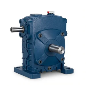
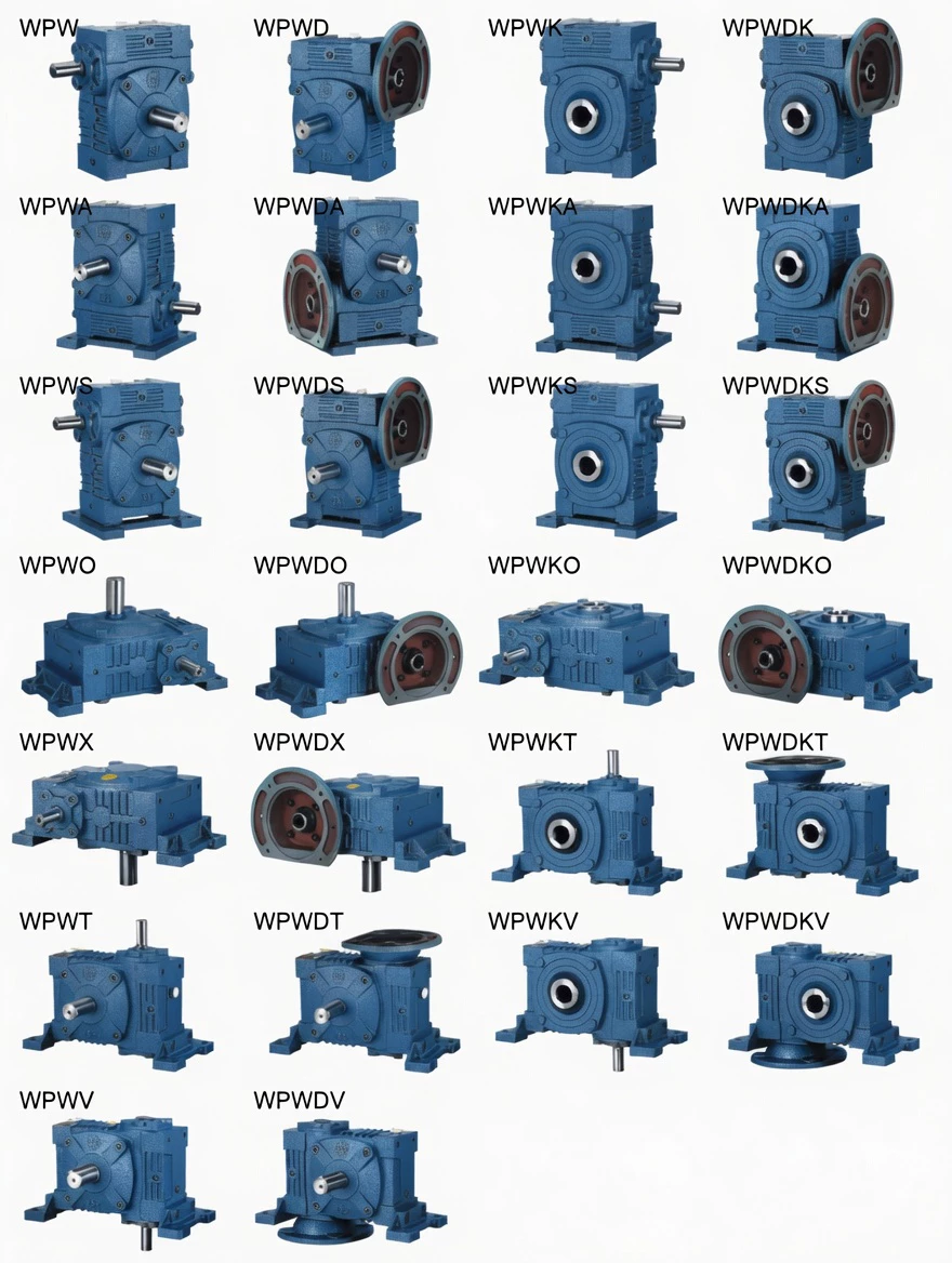
WPWDS Universal Speed Cast Iron Worm Gearbox
Motorised overhead drives — where the IEC motor mounts directly above the gearbox via flange connection and the installation must work in multiple orientations — combine two demanding specifications: overhead IEC motor geometry (D+S type) and universal housing versatility. The WPWDS Universal Speed Cast Iron Worm Gearbox delivers both: D-type IEC motor flange in the S-type (overhead) input position, WPW-series universal body, and D-split housing for field serviceability. The single product for all motorised overhead-motor universal drive requirements from ratio 1/5 to 1/60.
Technical Specifications — WPWDS

Key Parameters
| Parameter | Specification |
|---|---|
| Series | Universal Speed (WPWD+S) |
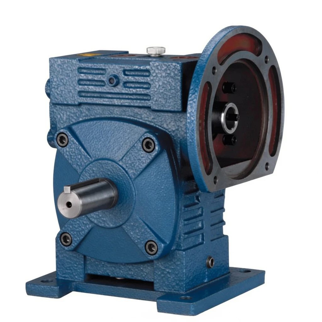
| Housing | D-type split cast iron |
| Input | IEC motor flange (D-type), S-type (from above) |
| Output | Solid shaft (horizontal) |
| Ratio | 1/5–1/60 |
| Size Range | 40–250 mm |
| Mounting | Foot-mount, D-split, IEC S-flange (overhead) |
| Housing Material | FC20+ grey cast iron (GG20) |
| Worm Wheel | Tin-bronze alloy ZCuSn10Pb1 |
| Worm Shaft | 20CrMnTi carburised & hardened, 55–60 HRC |
| Lubrication | N150–N220 (–30°C–40°C); N220–N320 (40°C–65°C) |
| Max Oil Temp | 95°C continuous |
| Weight Range | 7–481 kg |
| Key Feature | WPWDS: universal body + D-IEC flange (overhead S-type) — motorised overhead motor drive in universal W-housing with split-housing service access |
Size & Performance Data
| Size (mm) | Ratio | Input Power (kW) | Output Torque (Nm) | A (mm) | AA (mm) | AB (mm) | BB (mm) | Weight (kg) |
|---|---|---|---|---|---|---|---|---|
| 40 | 1/5–1/60 | 0.06–0.78 | 2.2–26.5 | 133 | 53 | 40 | 62 | 7 |
| 50 | 1/5–1/60 | 0.10–1.33 | 4.5–54.0 | 148 | 57 | 44 | 70 | 10 |
| 63 | 1/5–1/60 | 0.19–2.25 | 8.5–104 | 171 | 67 | 51 | 82 | 16 |
| 75 | 1/5–1/60 | 0.32–3.75 | 14.5–175 | 191 | 75 | 57 | 91 | 23 |
| 90 | 1/5–1/60 | 0.62–6.98 | 28–316 | 224 | 89 | 67 | 107 | 38 |
| 110 | 1/5–1/60 | 1.18–11.9 | 53–540 | 260 | 103 | 78 | 123 | 62 |
| 130 | 1/5–1/60 | 2.02–19.7 | 91–891 | 290 | 115 | 87 | 136 | 89 |
| 150 | 1/5–1/60 | 3.07–28.8 | 139–1304 | 329 | 131 | 100 | 155 | 128 |
| 175 | 1/5–1/60 | 5.13–45.9 | 232–2074 | 377 | 151 | 115 | 177 | 191 |
| 200 | 1/5–1/60 | 8.02–66.2 | 363–2993 | 424 | 170 | 130 | 199 | 267 |
| 250 | 1/5–1/60 | 14.0–106 | 633–4796 | 517 | 208 | 159 | 243 | 481 |
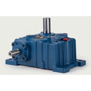
Universal W-Body Structure
The WPW-series universal housing is manufactured as a single FC20+ grey cast iron casting with bore positions, keyway orientations, and oil channels configured for the selected shaft direction. All 5 shaft direction configurations (A/B/C/D/E) use the same casting geometry with specific machining per configuration.
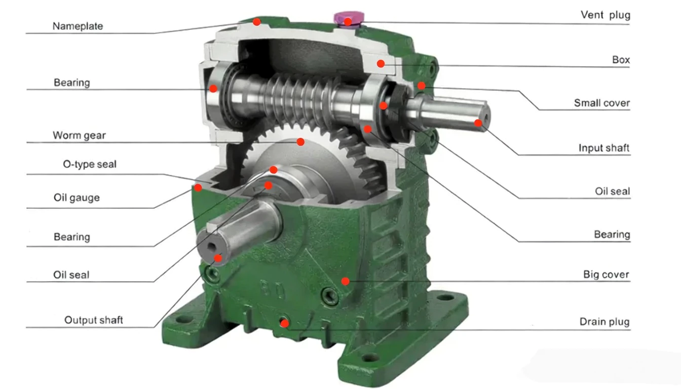
Hardened 20CrMnTi steel worm shaft with case-hardened tooth flanks (55–60 HRC). The worm shaft and its bearings are selected for the specific input orientation of the model — A-type (below), S-type (overhead), or bilateral — ensuring rated bearing life in the correct load direction.
Tin-bronze ZCuSn10Pb1 alloy worm wheel machined to mesh precisely with the hardened worm shaft. The bronze material provides excellent anti-seizure properties and wear-in characteristics for the worm gear mesh.
Output shaft in quenched-and-tempered steel with double-lip oil seals rated for the specific output orientation (horizontal, vertical upward O-type, vertical downward X-type, side T-type, or extended V-type). Seal selection matches the hydrostatic pressure requirements of the installed orientation.
Single-stage oil bath lubrication. Oil fill port, oil gauge, vent plug, and drain plug are positioned for the selected shaft direction configuration. Fill quantities are specified per configuration in the installation guide — do not use generic fill values across configurations.
FC20+ cast iron foot-mount base integrated with the housing casting. Four mounting holes for B3 foot mounting. The base orientation is fixed for the selected shaft direction configuration. For shaft-mount (hollow bore) applications, the torque arm boss provides housing restraint.
Core Features & Benefits
■ D-IEC Flange (S-Overhead) + Universal W-Body: Motorised Overhead Drive in Any Orientation
WPWDS integrates D-type IEC motor flange in S-type (overhead) input position with WPW universal body — providing direct overhead motor coupling in all 5 shaft direction configurations.
■ D-Split Housing for Elevated Service Access
D-split cover removal allows worm wheel inspection without crane access — motor stays mounted, driven shaft stays connected. Critical safety advantage for elevated overhead motor drive installations.
■ S-Overhead IEC Flange — Rated for Cantilevered Motor Weight
The WPWDS IEC flange is rated for cantilevered motor mounting in the overhead S-type position across all standard IEC motor frames within the size range.
■ 5 Shaft Direction Configurations Available
All 5 shaft direction configurations (A–E) available for WPWDS with D-IEC S-overhead flange. Full universal orientation coverage with motorised overhead input.
■ Full WP Ratio Range + Maximum Output Torques
1/5–1/60 in all orientations, output torques up to 4,796 Nm at size 250 — full WP performance in the motorised overhead universal configuration.
■ Anti-Corrosion Coating — Elevated Environment Grade
Epoxy/polyurethane coating for the condensation, outdoor/indoor boundary exposure, and chemical vapour environments common at elevated overhead drive positions.
Industry Applications — WPWDS
⚙ Motorised Overhead Universal Process Drives
Process plant engineers standardising on motorised overhead IEC motor drives across diverse equipment orientations use the WPWDS as their single motorised S-input universal product.
⚒ OEM Overhead Motor Universal Platform
OEM machine builders with IEC overhead motor requirements in multiple machine orientations specify the WPWDS as their motorised S-input universal gearbox platform.
⚔ Elevated Plant — Motorised Universal Standard
Elevated plant installations with IEC-motored overhead drives in multiple positions use the WPWDS for standardised motorised overhead drive maintenance and procurement.
⚊ Chemical & Process Equipment — Overhead IEC Universal
Chemical and process plant equipment with overhead IEC motor mounting in diverse orientations uses the WPWDS for their motorised overhead drive specification.
☷ Maintenance Fleet — Motorised S-Input Universal
Industrial maintenance departments managing motorised overhead drives across diverse equipment orientations standardise on WPWDS for maximum procurement and service simplification.
Why Choose WPWDS — Competitive Comparison
| Feature | Ever-power WPWDS | Alternatives |
|---|---|---|
| Motor Mounting | ✓ D-IEC flange S-overhead — direct | Coupling + overhead adaptor required |
| Universal Housing | ✓ 5-direction W-body — all positions | Orientation-specific S-type housing |
| Elevated Service | ✓ D-split — cover off, no crane | Full gearbox removal at height |
| Spare Parts | ✓ One SKU for all overhead orientations + IEC | Multiple models per orientation |
| IEC Motor Range | ✓ Full M8–M16 range | Same — single orientation housing |
| Certification | ✓ CE + ISO 9001 all orientations | Per-orientation certification |
Quality Control & Certifications

✎ ISO 9001:2000 Certified
Every WPWDS is manufactured, assembled, and tested under ISO 9001:2000 quality management. Our factory was among the first in this product category to achieve this certification.
✎ CE Marking
Full CE marking confirms compliance with EU Machinery Directive 2006/42/EC — covering safety, design standards, and manufacturing quality for all WPW-series universal configurations.
✎ Pre-Shipment Testing
Noise test (below 72 dB(A) at rated load), oil leak test (30-minute pressurisation), torque transmission test (output torque within ±5% of rated). Failed units are reworked — not shipped.
✎ Universal Configuration Quality
Each shaft direction configuration (A–E) is verified dimensionally for correct bore position, keyway orientation, and oil channel routing before leaving our production line.
Why Choose Ever-power for WPWDS
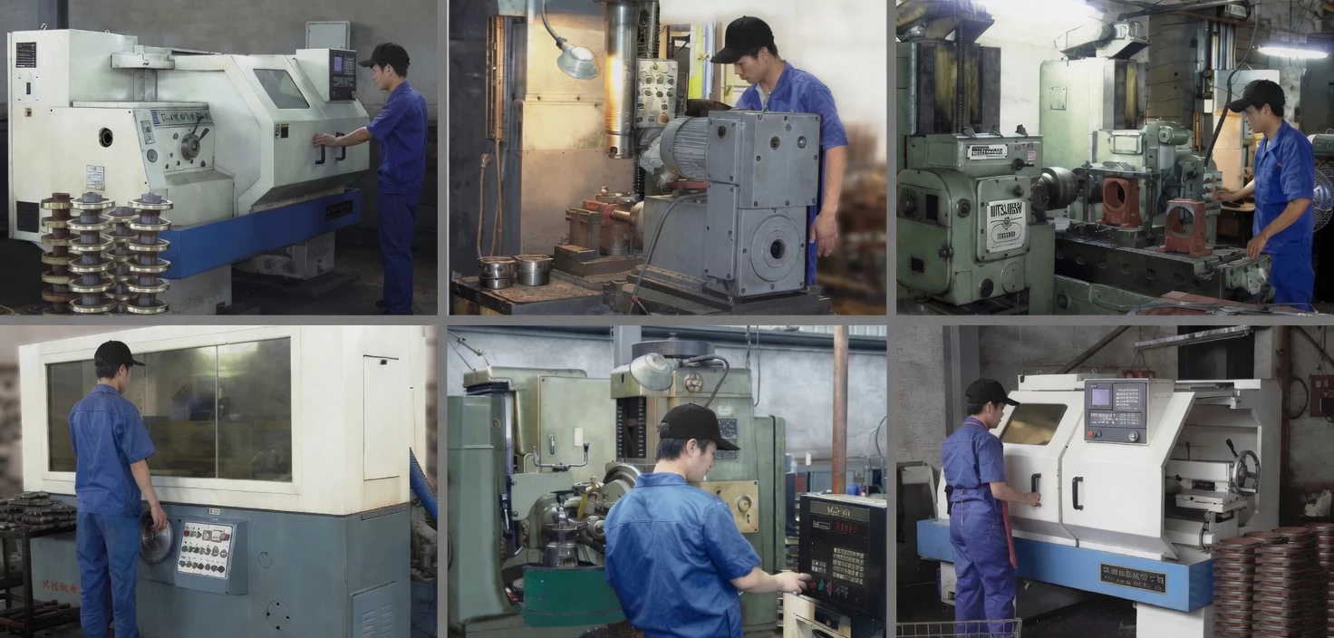
We have been manufacturing WPW-series universal cast iron worm gearboxes for over two decades. Our 5-shaft-direction production process — with orientation-specific quality checks — is a core competency of our manufacturing facility.
Our CNC machining centres maintain the bore position accuracy and keyway orientation tolerances required for consistent inter-part fit across all 5 shaft direction configurations of the WPW universal body.
We export the WPW series to Australia, Europe, Southeast Asia, the Middle East, and North America. Our export documentation, CE certification, and packing standards are optimised for international procurement.
Full OEM services: custom nameplating, paint colours, shaft dimensions, flange configurations, and documentation packages. Custom shaft direction combinations and output configurations available for OEM volumes.
Our application engineers provide WPW gearbox selection, load calculation, shaft direction selection, oil specification, and installation support. Email [email protected] with your application data.
The complete WPW universal series covers solid shaft, hollow bore, IEC flange, and extended shaft variants in all output directions — horizontal, vertical up, vertical down, side, and extended. One universal platform for all drive applications.
Customer Reviews & Case Studies
“WPWDS on our elevated overhead IEC motor drives. D-split means our maintenance team uses a platform to remove the cover — not a crane to lower the gearbox. This safety improvement alone justified the specification. Universal body covers all our overhead drive positions.”
Australia 🇦🇺
“WPWDS for our overhead motorised platform drives. S-input D-IEC flange in universal body covers all our elevated drive positions. Split housing for in-situ service at height. One product, all positions. Excellent practical engineering solution.”
Denmark 🇩🇰
“WPWDS drives our overhead IEC motor drives across multiple plant positions. Elevated mounting with overhead IEC motor is our plant standard. Universal body covers all drive positions from one product. Cast iron durability in our industrial environment is consistently excellent.”
India 🇮🇳
“WPWDS overhead IEC universal on our elevated processing drives. Motorised overhead configuration + universal body in one standard catalogue unit. Practical engineering product for multi-orientation elevated drives. Quality consistent across orders.”
Spain 🇪🇸
Frequently Asked Questions — WPWDS
Get Your WPWDS Quote Today
Whether you need one unit for a retrofit or hundreds for an OEM production run, Ever-power has the manufacturing capacity, ISO 9001 quality system, and WPW universal series expertise to deliver the WPWDS to your exact specification. Contact our engineering team — we respond within 24 hours.
✓ OEM & Distributor partnerships welcome ✓ Custom configurations available ✓ Global shipping