Mô tả
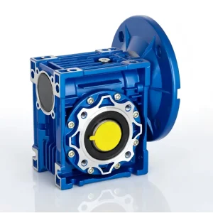
EP-NRV-E130 Aluminium Coaxial Worm Gearbox — Solid Shaft Input, Inline Output
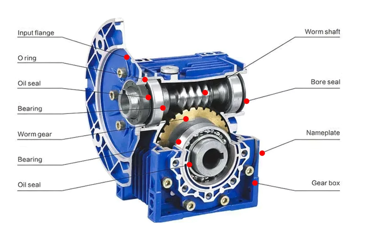
The EP-NRV-E130 is a extra-large inline shaft drive aluminium worm gearbox and an extra-large inline shaft-coupled unit in the NRV-E series, built around a 130 mm worm gear centre distance. It represents the most specialised configuration in the four-variant series: combining the solid 42 mm solid input shaft of the NRV series with the coaxial inline output of the NMRV-E series. The result is a worm gearbox that operates as a pure inline shaft-coupled reduction stage — accepting a shaft coupling, chain sprocket, or belt pulley on the input and delivering reduced speed on the same axis at the output, with no motor flange projection at either end and no 90-degree shaft offset. This configuration is engineered for paper mill coaxial shaft trains, heavy crane inline shaft drives, large extruder coaxial systems, and cement inline trains where the complete drive train must maintain a single shaft axis from source to load. With output torques up to 11000 Nm, ratios from 7.5–100:1, die-cast aluminium A360 housing, and IP65 shaft sealing, the EP-NRV-E130 serves paper mills and large-scale inline shaft-coupled industrial machinery across Australia and international markets. All six mounting positions are supported for maximum installation flexibility.
Technical Specifications — EP-NRV-E130
General Specifications
| Parameter | Specification |
|---|---|
| Model Number | EP-NRV-E130 |
| Series | NRV-E — Solid input shaft, coaxial inline output |
| Centre Distance | 130 mm |
| Output Configuration | Coaxial / Inline — same axis as input shaft |
| Max Output Torque | 11000 Nm |
| Reduction Ratios | 7.5–100:1 |
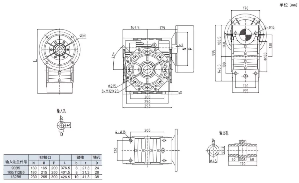
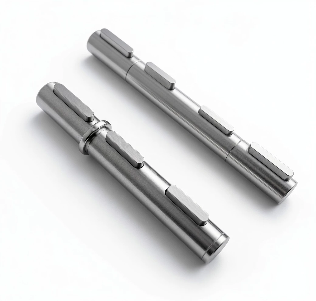
| Input Shaft Diameter | 42 mm solid |
| Input Shaft Keyway | 12×5.0 mm |
| Input Shaft Tolerance | h6 (precision ground) |
| Max Input Shaft Radial Load (Fri max) | 2100 N |
| Output Shaft Diameter | 60 mm (coaxial) |
| Max Recommended Input Power | 2.2 kW |
| Housing Material | Die-cast aluminium alloy A360 |
| Worm Wheel Material | Phosphor bronze |
| Worm Shaft Material | 20CrMnTi case-hardened steel, ground |
| Surface Treatment | Baked enamel paint (RAL 5010 blue) |
| Lubricant | ISO VG 220 worm gear oil, ~3.5 L |
| IP Rating | IP65 (shaft seals standard) |
| Ambient Temperature | -10°C to +40°C standard; up to +60°C with synthetic oil |
| Max Input Speed | 1,400 rpm (recommended); 1,800 rpm (max) |
| Approx. Weight | ~42 kg |
| Mounting Positions | B3, B6, B7, B8, V5, V6 |
| Output Configurations | Coaxial solid shaft (standard) / Coaxial output flange (FL) |
| Note | Double output shaft (DZ) not available — coaxial geometry |
| Standards | ISO 9001, CE marking |
Performance Selection Data (1,400 rpm Input)
| Ratio (i) | Output Speed (r/min) | Output Torque (Nm) | Input Power (kW) |
|---|---|---|---|
| 10:1 | 140 | 8000 | 2.2 |
| 15:1 | 93 | 9000 | 2.2 |
| 20:1 | 70 | 9584 | 2.2 |
| 25:1 | 56 | 10000 | 2.2 |
| 30:1 | 47 | 10400 | 2.2 |
| 40:1 | 35 | 11051 | 2.2 |
| 50:1 | 28 | 11500 | 2.2 |
Core Features & Benefits
◯Solid Shaft Input + Coaxial Output — The Ultimate Inline Shaft Drive
The EP-NRV-E130 combines both specialised features: a solid 42 mm solid input shaft (no motor flange) and a coaxial inline output shaft. This dual configuration produces the most compact possible inline shaft-coupled worm gearbox — ideal for multi-stage gear trains and inline shaft drives where both ends must be on the same axis with no flange projection.
△Shaft-to-Shaft Inline Reduction — No Axis Deviation
Unlike right-angle units, the NRV-E130 receives and delivers power along a single axis. Solid input shaft accepts couplings, sprockets, and pulleys; coaxial output connects to the driven load shaft. The result is a reduction stage that slots into any inline shaft train without introducing a 90-degree offset or motor flange bracket at either end.
◆Corrosion-Resistant Die-Cast Aluminium Housing
A360 die-cast aluminium provides inherent corrosion resistance for food processing, coastal, chemical, and humid environments. Baked enamel surface finish adds UV protection. 30–40% lighter than cast iron equivalents — critical for weight-sensitive elevated or moving structures.
■Identical Torque to All NRV{size} Variants
The NRV-E130 delivers the same 11000 Nm maximum output torque as the standard NRV130, NMRV130, and NMRV-E130 — all four variants share the same precision-ground worm set and phosphor bronze wheel. Only input/output configuration differs.
▶Static Self-Locking at Ratios ≥ 40:1
At 40:1 and above, worm geometry prevents back-drive under static load — useful in positioning, conveyor braking, and crane holding applications within inline shaft drive trains. Identical self-locking behaviour to all other NRV/NMRV variants using the same worm set.
●Full Mounting Position Flexibility — Six Orientations
B3, B6, B7, B8, V5, V6 mounting positions available. For V5/V6 vertical orientations, use the NRV-E lubrication guide (not standard NRV) to set the correct fill level for the coaxial internal geometry. Coaxial layout is particularly effective in vertical inline drive train columns.
All Four 130-Frame Variants — Which One Is Right for You?
All four variants in the 130-frame series share the same worm set, output torque ratings, and housing. Select based solely on input type (solid shaft vs IEC flange) and output direction (coaxial vs right-angle).
| Feature | EP-NRV-E130 ▶ | EP-NMRV-E130 | EP-NRV130 | EP-NMRV130 |
|---|---|---|---|---|
| Input Type | Solid shaft (no flange) | Hollow bore IEC flange | Solid shaft (no flange) | Hollow bore IEC flange |
| Output Direction | Coaxial / Inline | Coaxial / Inline | 90° Right-angle | 90° Right-angle |
| Max Output Torque | 11000 Nm | 11000 Nm | 11000 Nm | 11000 Nm |
| Best Use Case | Inline shaft-coupled gear trains | Inline motor-driven drives | Shaft-coupled right-angle drives | Direct motor right-angle drives |
| Motor Flange | No | Yes (IEC) | No | Yes (IEC) |
| Lateral Width | Narrowest inline | Narrow inline | Wider (90° shaft offset) | Wider (90° shaft offset) |
| Double Shaft DZ | Not available | Not available | Available | Available |
| Housing | Aluminium A360 (same) | Aluminium A360 (same) | Aluminium A360 (same) | Aluminium A360 (same) |
Application Sectors — EP-NRV-E130
The EP-NRV-E130 is the preferred choice for the following inline shaft-coupled drive system types where the solid input shaft and coaxial output together eliminate both motor flange projection and 90-degree shaft offset.
⚘ Paper Mill Coaxial Shaft Trains
Suitable NRV-E extra large solid shaft worm gearbox paper mill.
⚙ Heavy Crane Inline Shafts
Suitable coaxial shaft worm reducer crane inline shaft.
⚚ Large Extruder Coaxial
Suitable inline shaft worm gearbox extruder coaxial drive.
⚒ Cement Inline Shaft Trains
Suitable NRV-E worm reducer cement inline shaft train.
⚛ Mining Coaxial Gear Trains
Suitable extra large solid shaft coaxial worm gearbox.
Selection Guide, Mounting Positions & Shaft Details
How to Select the Correct Ratio
- Calculate required output torque: M₂ = 9,550 × P (kW) / n₂ (rpm), multiplied by service factor (fs = 1.0–2.5 per duty class).
- Determine actual input shaft speed: For belt/chain-driven inputs, n_input = n_primary × (D_primary / D_NRV-E). Use the actual input speed — not the primary motor rated speed.
- Find your ratio: i = n_input / n_output. Select the closest from 7.5–100:1.
- Confirm torque capacity and input radial load: Rated torque must exceed M₂ × fs. Calculate input shaft radial load from belt/chain tension and verify against Fri max = 2100 N. Step up to EP-NRV-E150 if either limit is exceeded.
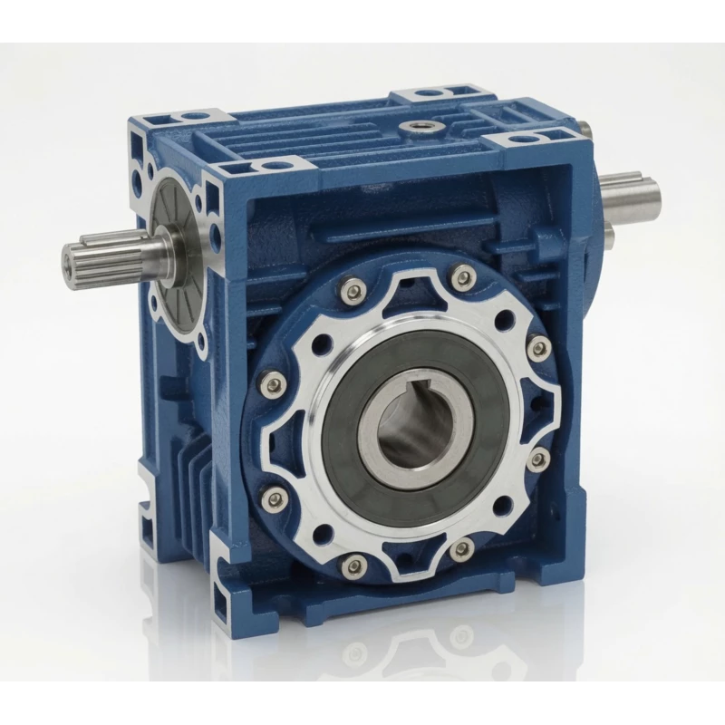
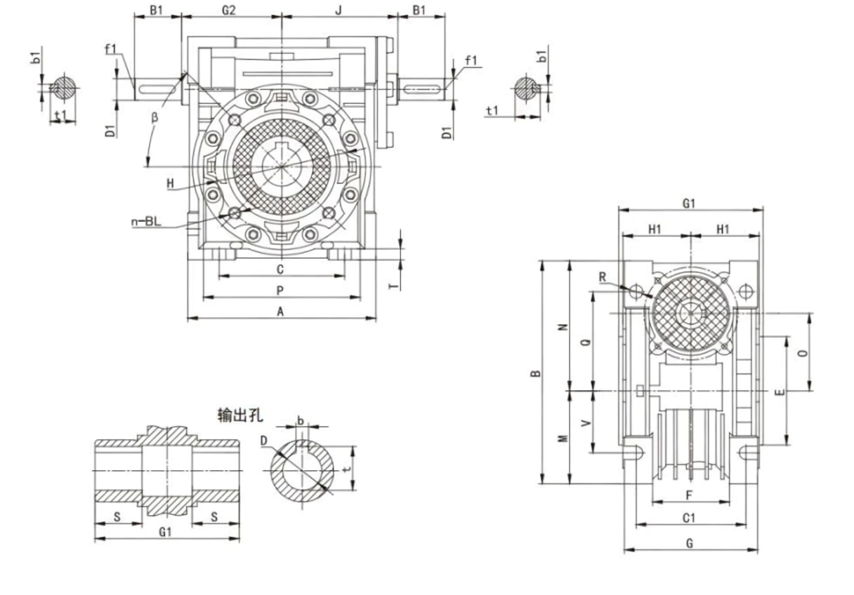
Input & Output Shaft Details
Input shaft: 42 mm solid solid | Keyway: 12×5.0 mm | Tolerance: h6 | Max radial load: 2100 N
Output shaft: 60 mm solid, coaxial (same axis as input) | With keyway | Standard solid shaft or FL flange option
60 mm with keyway on same axis as input. Default supply.
Direct bolt-on flanged connection coaxial with input axis. Suffix: FL.
Double output shaft (DZ) is NOT available in the NRV-E coaxial series.
Mounting Positions
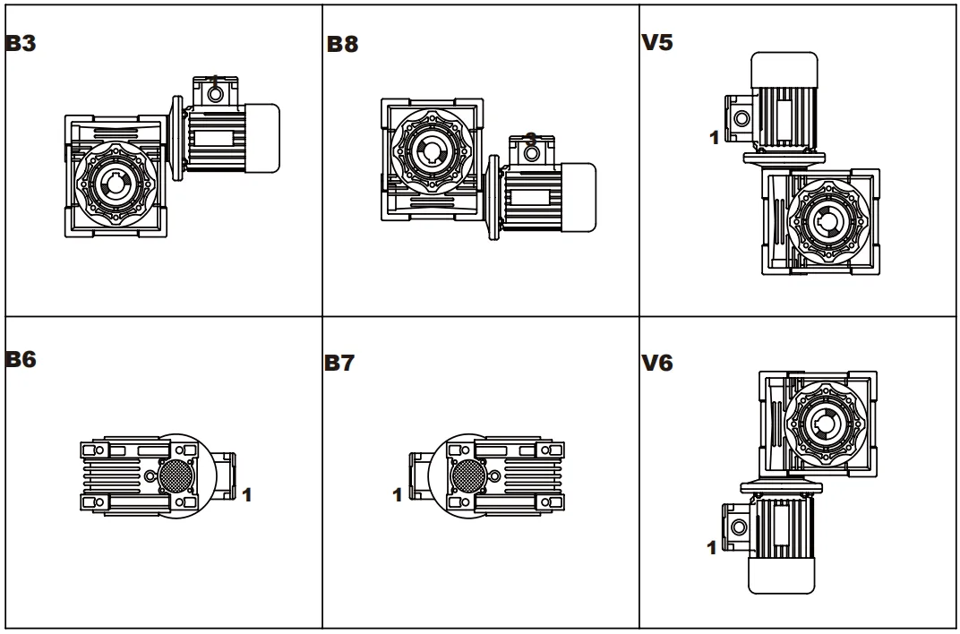
| Position | Description | Shaft Orientation | Oil Level Note |
|---|---|---|---|
| B3 | Horizontal foot mount | Inline horizontal shaft — input and output facing opposite ends | Standard fill level — default |
| B6 | Foot mount, output shaft down | Inline vertical shaft downward | Reduce oil by ~15% |
| B7 | Foot mount, output shaft up | Inline vertical shaft upward | Increase oil by ~15% |
| B8 | Foot mount, 180° rotated | Inline horizontal reversed | Standard fill level |
| V5 | Flange mount, shaft down | Inline vertical downward | Reduce oil — use NRV-E lube guide |
| V6 | Flange mount, shaft up | Inline vertical upward | Increase oil — use NRV-E lube guide |
Important: For NRV-E V5/V6 vertical orientations, use the NRV-E lubrication diagram to set the correct oil fill level. The coaxial internal geometry requires a different fill level from both the standard NRV and NMRV-E guides.
Frequently Asked Questions — EP-NRV-E130
▶ What inline shaft drive applications suit the EP-NRV-E130?
The EP-NRV-E130 is specified for paper mill coaxial reel drive shaft trains, heavy gantry crane inline shaft mechanisms, large extruder coaxial secondary drive stages, and cement plant inline belt/chain-driven conveyor trains — delivering up to 11,000 Nm through a 60 mm coaxial output shaft without any motor flange projection or 90-degree output offset.
▶ What is the input shaft specification of the EP-NRV-E130?
Solid 42 mm input shaft with 12×5.0 mm keyway, h6 tolerance. Maximum input shaft radial load (Fri max) is 2,100 N. For high-tension chain drives near this limit, a bearing support bracket is mandatory. Use a torque-rated flexible coupling for motor-to-shaft connections.
▶ How does the NRV-E130 compare to the NMRV-E130 for paper mill drives?
Both deliver identical 11,000 Nm coaxially through a 60 mm output shaft. The NMRV-E130 mounts a motor directly via IEC flange; the NRV-E130 connects via solid shaft to an upstream gearbox or shaft drive. Choose NRV-E130 for paper mill drive trains where the winding drive is powered by a shaft-connected primary reducer, not a directly-flanged motor.
▶ How much lubricant does the EP-NRV-E130 require?
Approximately 3.5 litres of ISO VG 220 worm gear oil in B3 orientation. For V5/V6 vertical mounting, consult the NRV-E lubrication diagram for the correct coaxial fill level. Oil change every 5,000 hours (mineral) or up to 10,000 hours (synthetic).
▶ What is the static self-locking behaviour of the EP-NRV-E130?
Static self-locking (η < 0.5) is present at 40:1 and above, preventing output back-drive under static load. At 30:1, self-locking is borderline. For safety-critical load retention in paper winding drives and crane inline mechanisms, install a certified external holding brake regardless of ratio.
▶ Can the EP-NRV-E130 be installed in all six mounting positions?
Yes — B3, B6, B7, B8, V5, and V6 are all supported. The solid input shaft exits one side of the housing; the coaxial output exits the opposite end. In vertical orientations (V5/V6), the long axial assembly (input coupling + gearbox + output coupling) must be adequately supported to prevent bending moment on the gearbox housing.
Customer Reviews
★★★★★
“EP-NRV-E130 units installed in the inline coaxial drive train of our reel drive assembly at our newsprint mill. Solid 42 mm input shaft from the primary gearbox coupling, coaxial 60 mm output to the reel shaft — maintaining the inline axis through the entire drive train on a single axis. Torque at 30:1 is exactly right for our web tension. Outstanding in the humid mill environment.”
Brian Hartley — Paper Mill Drives Australia
Australia
★★★★★
“Specified as the final reduction stage in our heavy gantry crane long-travel inline shaft drive trains. The NRV-E130 connects from the primary gearbox output to the wheel axle shaft coaxially — no lateral offset, no bracket. Self-locking at 40:1 provides secure holding between travel commands. Excellent reliability.”
Johan Lindberg — Crane Engineering Scandinavia
Sweden
★★★★★
“Our cement raw meal conveyor inline shaft drives use EP-NRV-E130 units at 30:1. Solid shaft input from belt-driven primary gearbox, coaxial output to conveyor head shaft — maintaining the full drive on one axis within our narrow cement bay. IP65 sealing handles the cement dust environment. Very satisfied with performance and durability over two years.”
Diego Herrera — Cement Engineering Solutions
Peru
Related Products & Accessories
⚙ Input Connection Options
Flexible jaw / disc / gear couplings for 42 mm solid shaft.
Chain sprockets (verify tension against Fri max 2100 N).
V-belt and toothed belt pulleys.
Bearing support bracket for high-tension chain/belt inputs.
⚒ Output Options
■ Coaxial solid shaft (standard, 60 mm)
■ Coaxial output flange (FL suffix)
◆ DZ double shaft not available in NRV-E series
■ Torque arm for torque reaction mounting
◆ All Four 130-Frame Variants
■ EP-NRV-E130 — this unit (shaft in, coaxial out)
■ EP-NMRV-E130 — flange in, coaxial out
■ EP-NRV130 — shaft in, 90° right-angle out
■ EP-NMRV130 — flange in, 90° right-angle out
■ EP-NRV-E150 — next frame size up
Ready to Order the EP-NRV-E130?
Request a quote, technical selection support, or enquire about OEM and distributor partnership opportunities for Australian and international markets.
▼ Distributor & OEM partnerships welcome — volume pricing available